ResidentialEnergyLaboratory.com
Links:Home Page
House Construction Details
Net Energy Use
Energy Use Details
Costs and Payback for Net-Zero
Infrared Images of REL
Energy Efficient Design
Comparison of PV Systems
R-Value of Cellular Shades
Energy Codes for Windows
Solar PV Raw Data
Related Links
About Us
Contact
Site Map
| Energy Use Details - Heat Recovery Ventilation System
The purpose of the heat recovery ventilation (HRV) system
is to provide a flow of fresh air into the Residential Energy Laboratory (REL)
and to exhaust a similar flow of stale air out of the REL, but to transfer a
majority of the heat energy of the stale air to the fresh air before the stale
air is exhausted. In cold weather, the
fresh air is heated by this process, while in hot weather, the fresh air is
cooled by the stale air if the indoor temperature is cooler than the outdoor
temperature.
To put it another way, many houses use an exhaust fan to
vent stale air from the home. These pull
in fresh air through unintended leaks in the house. So, for example, if it is -15.6˚C (4˚F)
outside, then the fresh air will have to be heated from that temperature to the
indoor air temperature. In the case of
the HRV installed in the REL running on low speed (~ 33 l/s or ~70 CFM) with an
outside air temperature of -15.6˚C (4˚F), the fresh air enters the house at 9˚C
(48˚F) while the indoor thermostat is set at 19˚C (67˚F). Use of the HRV results in a significant
energy savings in heating the fresh air, with about 1120 W (3800 Btu/hr) of
power being transferred from the stale air to the fresh air at this particular
condition. The power to run the HRV at
this condition was 28 W, so this is hugely favorable from an energy standpoint. The temperature transfer efficiency at this
condition was measured to be 71.9%.
As an aside, some of the inlet air heating occurs in the
insulated ductwork upstream of the HRV, so the 9˚C (48˚F) temperature at the
outlet of the HRV would be lower with shorter inlet ductwork. The heat transfer in the ductwork is not
included in the figure given for the heat transfer in the HRV. The heat transfer in the ductwork is, of
course, an energy loss from the house.
Similar measurements at the high flow condition in the
HRV at about 66 l/s (140 cfm) at an outside air temperature of -6˚C (22˚F) resulted
in the fresh air to the house being preheated to 10˚C (50˚F), transferring 1680
W (5720 Btu/hr) of power to the inlet air stream. The power consumed by the electric motors in
the HRV is 71 W at the high flow condition, so again, this is very efficient
from an energy standpoint. The
temperature transfer efficiency at this condition was measured to be 68.4%,
lower than the low flow condition due to the shorter residence time in the heat
exchanger.
The HRV with the performance as described above was a
Venmar AVS EKO 1.5, Model 43900. It uses
fans with brushless DC motors (BLDC) , more commonly known by their trademarked
name electronically commutated motors or ECMs, to minimize energy
consumption. The fans are the only
moving parts for this HRV. The heat
transfer is performed passively through a fixed heat exchanger, and the
operation is easy to understand by examining Figure 1, which shows the HRV with the front cover removed. The heat exchanger can be crudely described
as like a large collection of very small soda straws arranged in alternating
rows at right angles to each other, with the spaces between them filled in with
plastic. Fresh air enters the HRV from
the top right in Figure 1, and is pulled through the heat exchanger by the fan
partly visible on the bottom left. The
same mass flow of stale air enters the HRV on the top left, and is pulled
through the heat exchanger by the fan partly visible on the bottom right. After passing through the fans, the air flows
turn vertically upward and travel to the top of the HRV unit. In the case of the fresh air, it is ducted to
the outlet side of the natural gas fired, hot-air furnace. In the case of the stale air, it is exhausted
from the house. In the winter time, the
fresh air upstream of the HRV and the stale air downstream of the HRV can be
significantly below the crawl space temperature, so those two ducts are
insulated to minimize cooling of the crawl space. In the summer time, those two ducts can be
significantly warmer than the crawl space, so minimizing heat transfer is still
important that time of year.
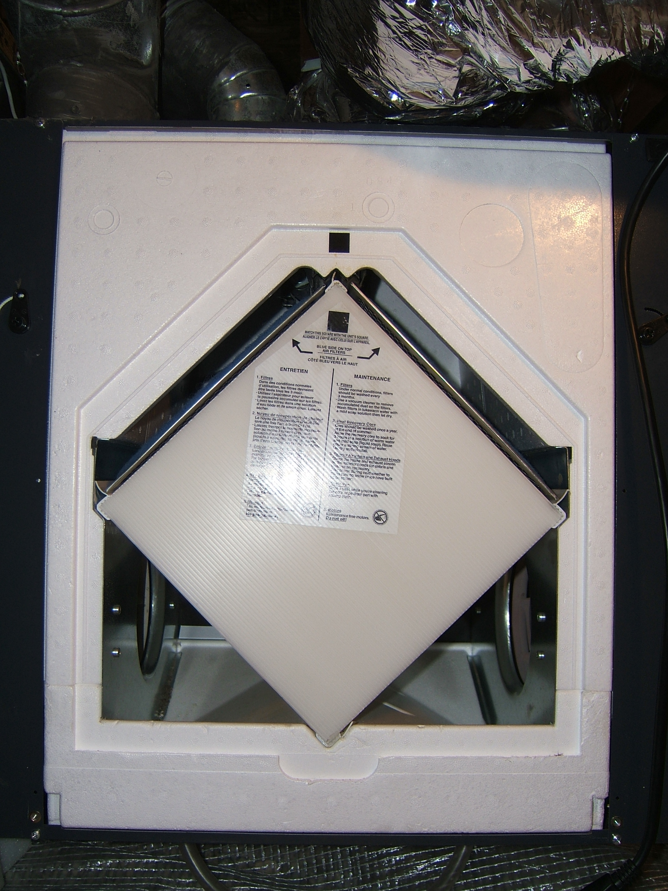
Figure 1.
HRV with Front Cover Removed Showing Flow of Fresh Air from Top Right and Stale Air from Top
Left.
There is an electrically controlled vane just above the
top of the heat exchanger, not visible in Figure 1, that separates the two
chambers on the top left and top right of the heat exchanger when the HRV is
used to precondition the fresh air. This
vane can also be rotated such that those two chambers communicate (are
connected), and the fresh air inlet to the HRV is blocked. This allows the stale air to flow from the
top left chamber to the top right chamber and then through the heat exchanger
with no cross flow. In this case, only
the fan on the bottom left is operated.
This simply recirculates the stale air through the house.
The recirculation mode is important in two cases. In the first case, when the inlet air
temperature is less than -5˚C (23˚F), the recirculation mode is alternated with
the standard mode to defrost the heat exchanger by warming it during the
recirculation period. In the second
case, the recirculation mode may be used to even out temperature differences in
the house without bringing in fresh air.
The recirculation mode may be selected for 100% of the cycle, or it may
be alternated with the standard cycle where the standard cycle runs on low
speed for 20, 30, or 40 minutes per hour, with the balance of the time spent in
the recirculation mode. In the
recirculation mode, the single fan on the bottom left in Figure 1 runs on high
speed, while in the standard HRV mode, the two fans can be operated on low or
high speed (user selectable). The HRV is
often used with some amount of recirculation at the REL to distribute the
passive solar heating that occurs preferentially at the south end of the
house.
The electrical energy consumption of the Venmar HRV was
low at all conditions, with the actual values measured by a Kill-A-Watt meter
as shown in the table below.
Electrical Power Consumption of Venmar Eko
1.5 HRV
|
Mode of Operation
|
Power Consumption (W)
|
|
Minimum speed with 100% fresh air
|
28
|
|
Maximum speed with 100% fresh air
|
71
|
|
Minimum speed with fresh air 20 min/hr*
|
46
|
|
Minimum speed with fresh air 30 min/hr*
|
41
|
|
Minimum speed with fresh air 40 min/hr*
|
38
|
|
100% Recirculation mode at max. speed
|
60
|
* The balance of the hour in recirculation mode, which uses a single fan at high speed. .
APPENDIX
For those interested in getting a better “feel” for the
operation of an HRV, some detailed measurement results are presented below for
the Venmar Eko 1.5 HRV operated at the Residential Energy Laboratory. Temperature measurements were taken in the fresh
and stale airstreams in the ducts just upstream and downstream of the HRV. These were accomplished by drilling 3.97 mm (5/32”)
holes in the ducts, and inserting an Omega thermister measuring 102 mm (4”)
long and 3.175 mm (1/8 “) in diameter (Part No. TH-10-44046 -1/8-4-40) into the
ducts while the HRV was operating. The
thermister output was read using a Radio Shack multimeter set on the ohm-meter
scale. The calibration table supplied by
Omega was fit with a third-order polynomial to relate the lne(R)
to the temperature in ˚C, as shown in Figure A-1 below.
Figure A-1.
Plot of data supplied by Omega Corp. to Determine Temperature from the
Measured Thermister Resistance.
Detailed measurements were taken of the HRV performance
during a procedure to balance the two airflows, the fresh air into the house
and the stale air exhausted from the house.
These flows are sometimes purposely unbalanced to provide a net positive
or negative pressure in a building, but in this case, the object was to balance
the airflows. This is normally done by
measuring pressure differentials across the heat exchanger, but since the HRV
was already instrumented for temperature measurements, it was determined that
more precise measurements could be performed using the temperature data.
The objective was to balance the temperature gain in the
fresh air with the temperature loss in the stale air to within about 5%. A number of measurements were taken at both
low and high speed fan operation. Data
are shown below for low speed fan operation in Table A-1 and for high speed fan
operation in Table A-2. Note that for
these conditions, the heat transfer power, and, by implication, the fan speeds were
balanced to within 1% for low speed fan operation, and to within 4% for high
speed. Measurements at other conditions
provided similar results. Balancing the temperature
differentials for fresh and stale air required adjusting dampers in the
airstreams downstream from the fans.
Note that the power transferred was more than ten times the power
consumption by the fans at these conditions with a relatively large temperature
differential available.
Table A-1.
HRV Operation on Minimum Speed.
|
Parameter
|
˚C or SI units
|
˚F or American units
|
|
Date
|
2/4/2012
|
2/4/2012
|
|
Time
|
7:00
|
7:00
|
|
Speed
|
Low
|
Low
|
|
Airflow (l/s, cfm)
|
~33
|
~70
|
|
Indoor temp. (˚C, ˚F)
|
19.3
|
66.7
|
|
Relative humidity (%)
|
23
|
23
|
|
Water vapor partial press. (kPa)
|
0.52
|
0.52
|
|
Saturation vapor pressure at stale air out temp. (kPa)
|
0.49
|
0.49
|
|
Condensation state air in HRV?
|
Likely
|
Likely
|
|
Outdoor temp. (˚C, ˚F)
|
-15.7
|
3.8
|
|
Fresh air into HRV temp. (˚C, ˚F)
|
-10.9
|
12.4
|
|
Fresh air out of HRV temp. (˚C, ˚F)
|
8.8
|
47.8
|
|
Stale air into HRV temp. (˚C, ˚F)
|
16.5
|
61.7
|
|
Stale air out of HRV temp. (˚C, ˚F)
|
-3.0
|
26.5
|
|
ΔT fresh air across HRV (˚C, ˚F)
|
19.7
|
35.4
|
|
ΔT stale air across HRV (˚C, ˚F)
|
19.5
|
35.1
|
|
Ratio stale to fresh airflow
|
1.01
|
1.01
|
|
Temp. transfer efficiency (%)
|
71.9
|
71.9
|
|
Temp. change from outside to HRV inlet (˚C, ˚F)
|
4.8
|
8.7
|
|
Power transferred to fresh air in HRV (W, btu/hr)
|
623
|
2126
|
Table A-2.
HRV Operation on Maximum Speed.
|
Parameter
|
˚C or SI units
|
˚F or American units
|
|
Date
|
2/3/2012
|
2/3/2012
|
|
Time
|
19:15
|
19:15
|
|
Speed
|
High
|
High
|
|
Airflow (l/s, cfm)
|
~65.8
|
~140
|
|
Indoor temp. (˚C, ˚F)
|
|
66.6
|
|
Relative humidity (%)
|
29
|
29
|
|
Water vapor partial press. (kPa)
|
0.65
|
0.65
|
|
Saturation vapor pressure at stale air out temp. (kPa)
|
0.75
|
0.75
|
|
Condensation state air in HRV?
|
Unlikely
|
Unlikely
|
|
Outdoor temp. (˚C, ˚F)
|
-5.8
|
21.6
|
|
Fresh air into HRV temp. (˚C, ˚F)
|
-4.5
|
23.9
|
|
Fresh air out of HRV temp. (˚C, ˚F)
|
10.2
|
50.3
|
|
Stale air into HRV temp. (˚C, ˚F)
|
17.0
|
62.5
|
|
Stale air out of HRV temp. (˚C, ˚F)
|
2.8
|
37.0
|
|
ΔT fresh air across HRV (˚C, ˚F)
|
14.7
|
26.4
|
|
ΔT stale air across HRV (˚C, ˚F)
|
14.2
|
25.5
|
|
Ratio stale to fresh airflow
|
1.04
|
1.04
|
|
Temp. transfer efficiency (%)
|
68.4
|
68.4
|
|
Temp. change from outside to HRV inlet (˚C, ˚F)
|
1.3
|
2.3
|
|
Power transferred to fresh air in HRV (W, btu/hr)
|
931
|
3177
|
|